Please read thoroughly before starting assembly
Note: some of the lead spacing issues have been corrected in V1.1 of the circuitboard, but carefully form leads to hole spacing so you don't pull leads off capacitors.
Zener test circuit is shown at bottom of this page.
Please read the First Things First section before starting your kit.
| A hint when testing, troubleshooting, or tuning the rig. In the initial wiring into the enclosure kit, or your own enclosure, do not attach all front and rear panel parts first. Estimate the lengths of all wires or use the lengths we specify, and wire the kit in the open on an insulated static free work bench. This way you can easily test or replace parts on the board. Once the rig is fully functional then install it into the enclosure. |
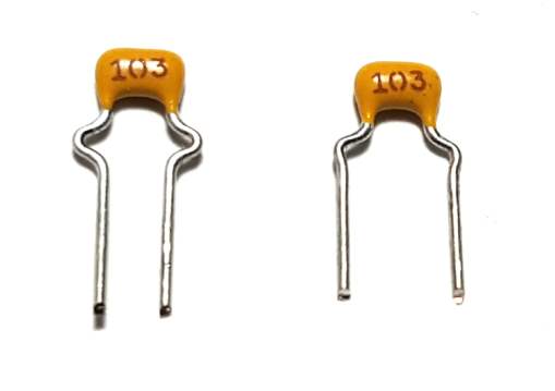
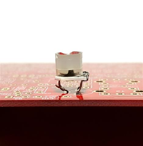
On some capacitors it is important to carefully bend capacitor leads to fit easily into holes. If you force leads not formed, you may break lead off capacitor body. Because of various manufacturers, the lead spacing may vary greatly. The picture below shows leads of a preformed capacitor (left) from manufacturer, and leads that will be bent by you (right).
| Hint: If you don't have access to a good magnifying glass and have a Smartphone, use your Smartphone camera to take a picture of the small printing and zoom in to magnify just like the pictures above and below. Note: All the pictures on this website were taken with a Galaxy S6 Smartphone. |
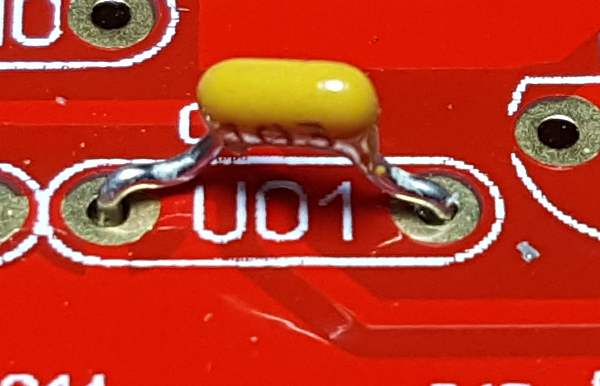
When the capacitor is mounted it should look like this:
D1 - 1SV149 orientation. Must be installed as shown below.
R24 - 500 ohm potentiometer lead spacing
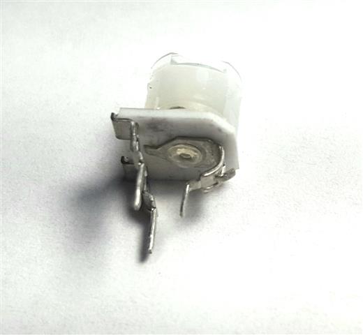
Some pots that come with the kits may not have the lead spacing that the board is laid out for. You will need to bend the wiper pin (right pin in picture) slightly with needle nose pliers as shown and straighten the other two leads and bend the two left pins slightly towards the center. Later versions of the board have two pads to accommodate different trimpot lead spacing.
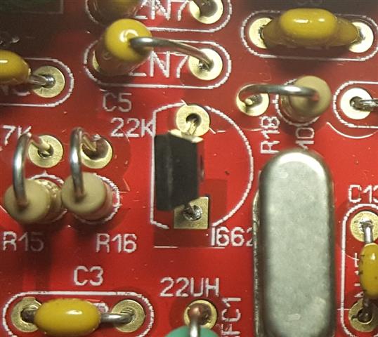
Insert pot on board and make sure its straight like the picture below and solder.
Version 1.1 of the boards have a second wiper pad so you won't
need to bend any pins.
Diode D11 and D12 (if used) are identified as follows:
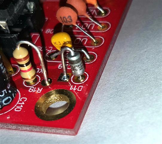
D11 (1N5236 7.5V zener) has a silver body as of this run of parts.
Note the cathode or banded end goes into the square pad as shown above. Some
boards that come back for repair have the banded end going into the round pad.
Caution must be noted on the 7.5 volt and 33 volt zeners. They could be clear glass type like the 1N4148 or they may have a silver coating on the case. Some batches have case coatings reversed. In any case, use a magnifying glass to verify the correct numbers. 1N5236 7.5 V, 1N5257 33V. If you need to verify which diode is which, scroll down to bottom of page for a cheap zener tester.
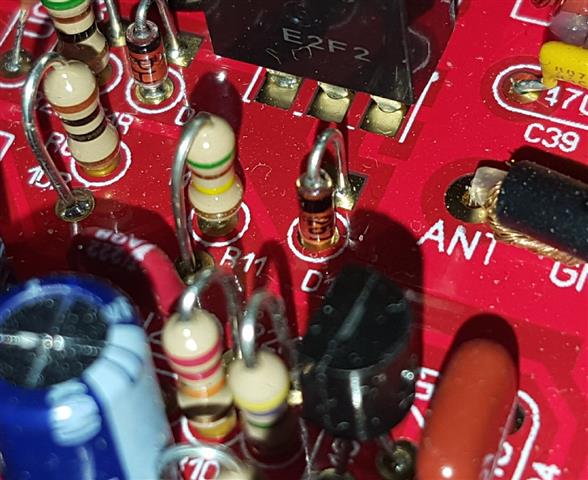
D12 (1N5257 33V zener) has a glass body and looks like a 1N4148. Do not mix them up!
D12 comes in a bag with D11 and separate from other 1N4148 glass diodes.
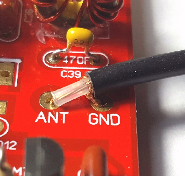
Closeup view of RG174 soldered to board.
As of this board run you may have to remove a few strands of braid to get it to
insert into board. Later boards have larger pad holes.
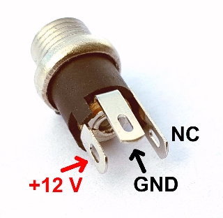
Rear panel power connector wiring.
Center pin is +12 volts!
5.5 x 2.1mm coaxial power connector
CAUTION: If using a transformer "wall wart", make sure it is regulated. Most just have a rectifier and capacitor inside and the voltage can be as high as 17 volts even if marked as 12 volts. The newer switching supply wall warts are closer to 12 volts but note that it could possibly generate noise that could appear on the receiver.
Some components will have tape holding the leads together. These parts are normally used in automated component insertion equipment. The leads are long enough that you can just cut the leads close to the tape rather than pulling tape off. Some of the adhesive may remain on lead ends and inhibit a good solder joint if adhesive gets stuck in the through hole.
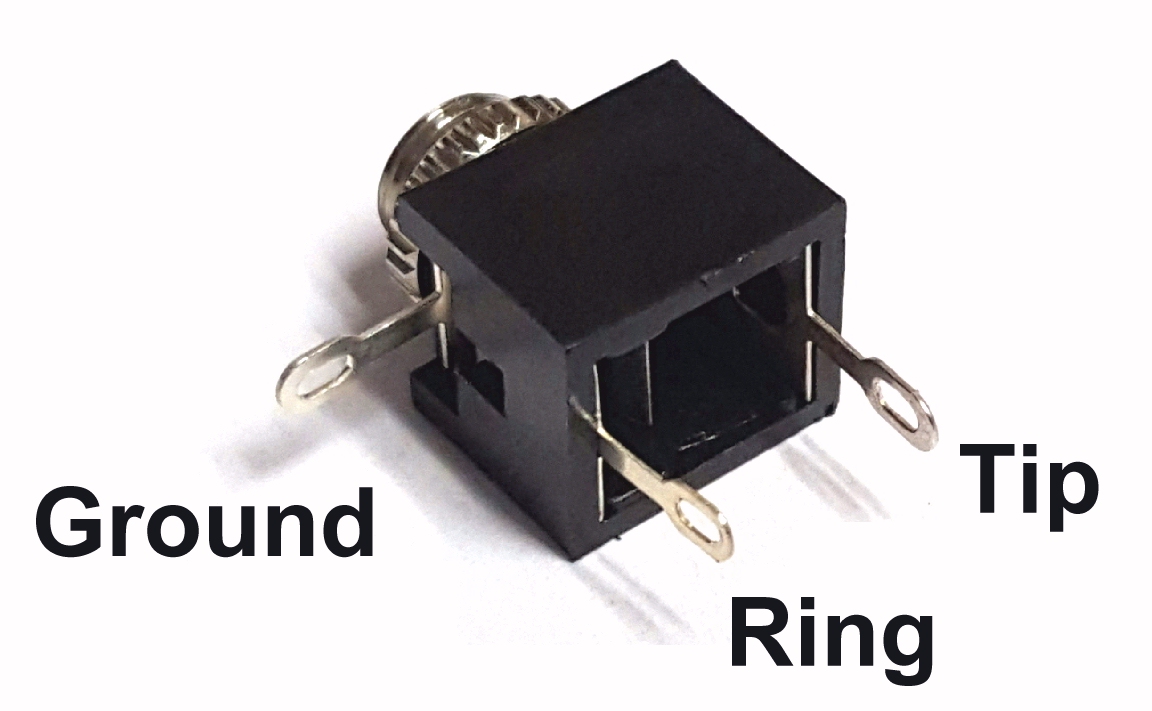
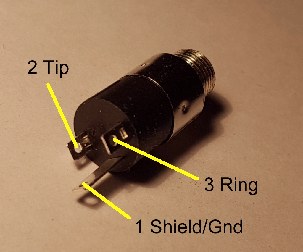
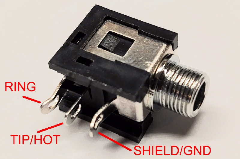
Headphone jack
See new page describing the variations and hookups for these jacks
You must decide what type of earphones or headphones you will
use. The most common is a stereo type MP3 earbuds or Walkman type earphones or
more comfortable high quality headphones that have a 3.5mm plug.
Stereo plugs will have a tip, ring, and sleeve or 3-circuit plug. If this is
your case just tie the tip and ring together going to J3 Pin 2. Just remember
that if you plug a mono 2-circuit plug into this jack it will short the output
to ground. No damage will occur to the amplifier, it just won't work.
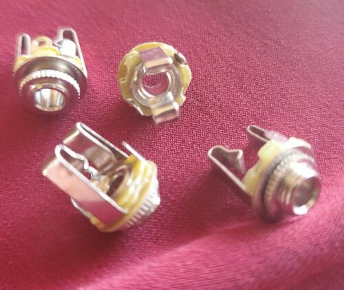
Some jacks that come with the kit are open frame.
Key Jack
For the key jack tie the ground to chassis via the blue wire and the tip to the key wire (yellow)
Modular Headers
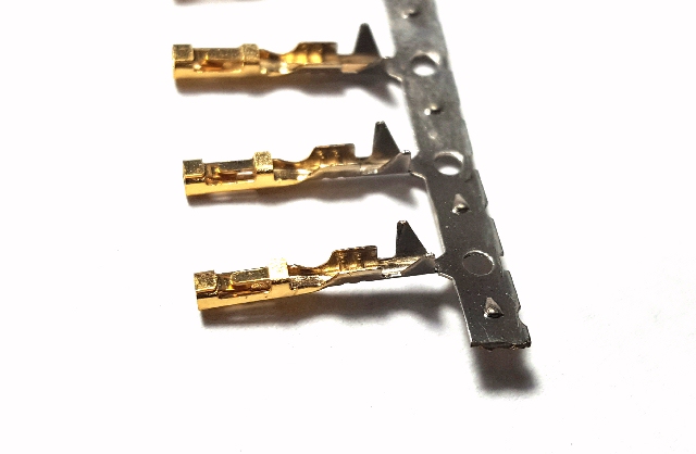
Your kit includes pins for the modular connector housing should you decide
not to wire directly board.
| If you do decide to wire directly to the board, do not assemble the board into the enclosure first. Wire up all the front and rear pots and connectors and run your tests and adjustments with the board out of the box on your work bench. Once happy with everything, attach the board and attach the front and rear parts. The only unsoldering you will need to do is the BNC connector. |
If you decide to use header connectors instead of wiring
directly to board, follow the instructions below.
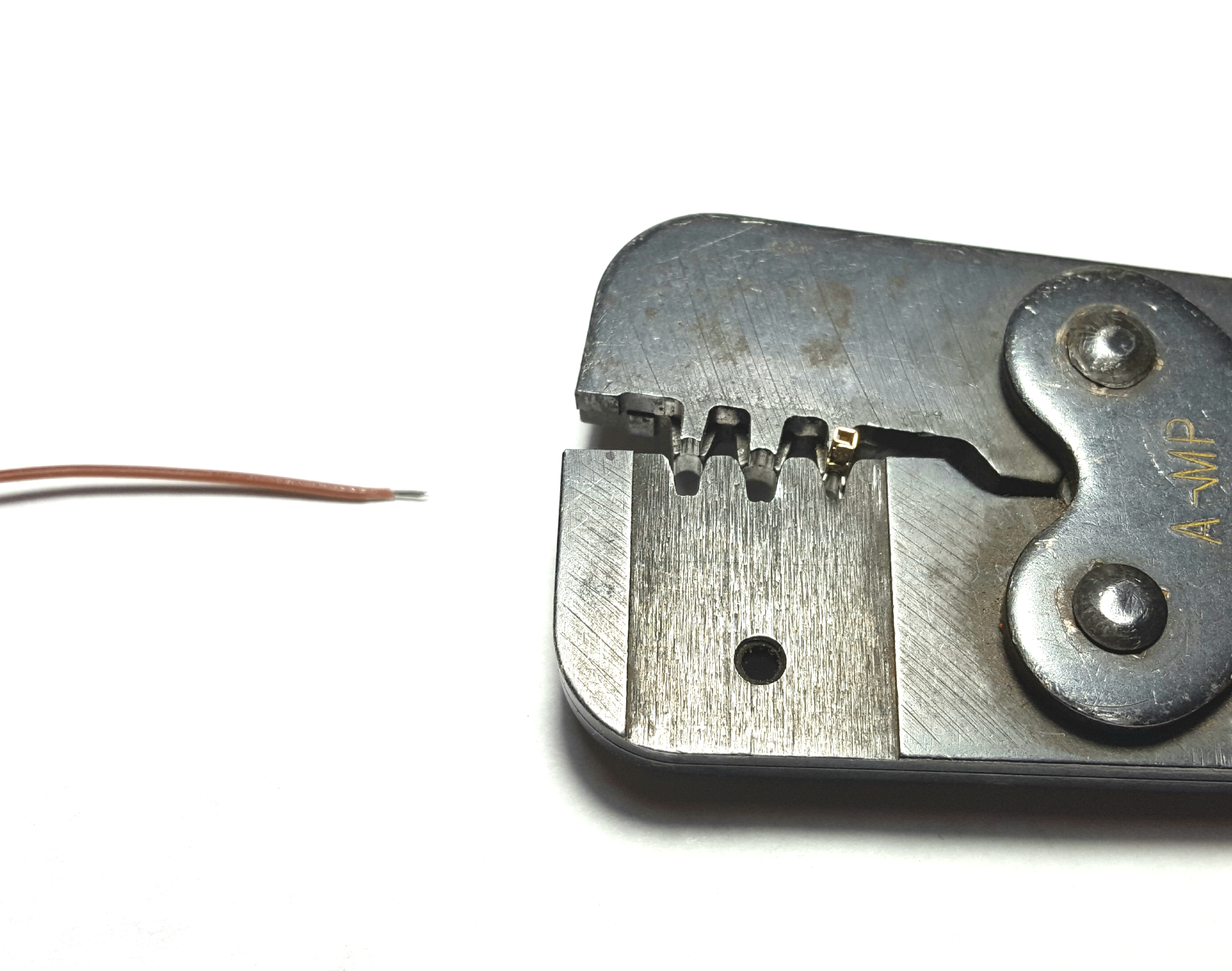
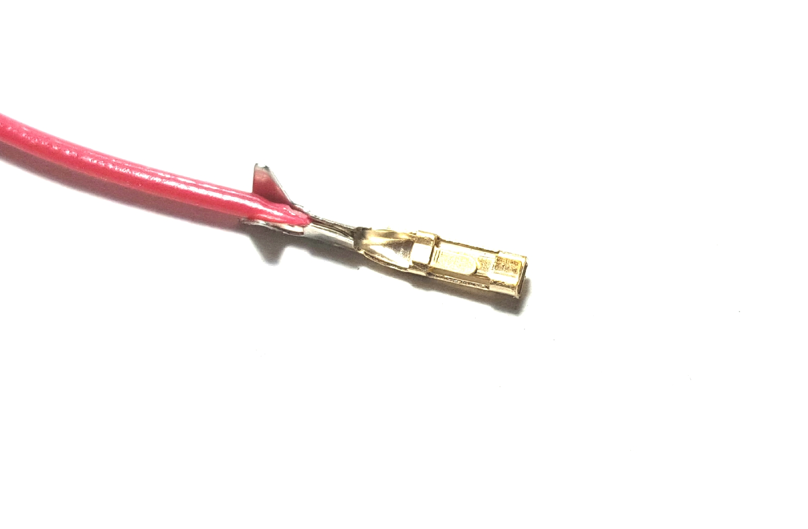
Strip wires as shown above. If you are fortunate to have a good crimper, set the
pin as shown.
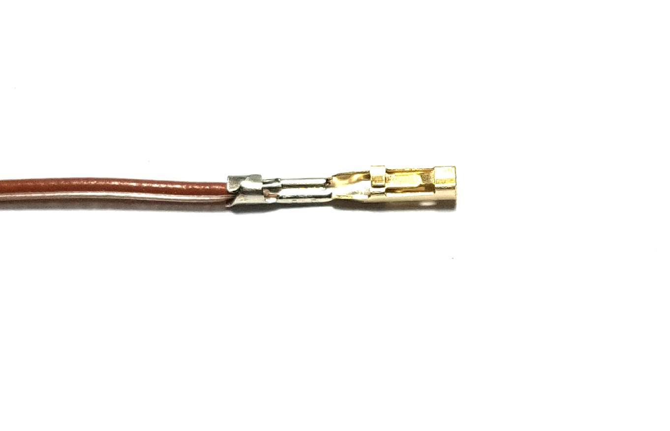
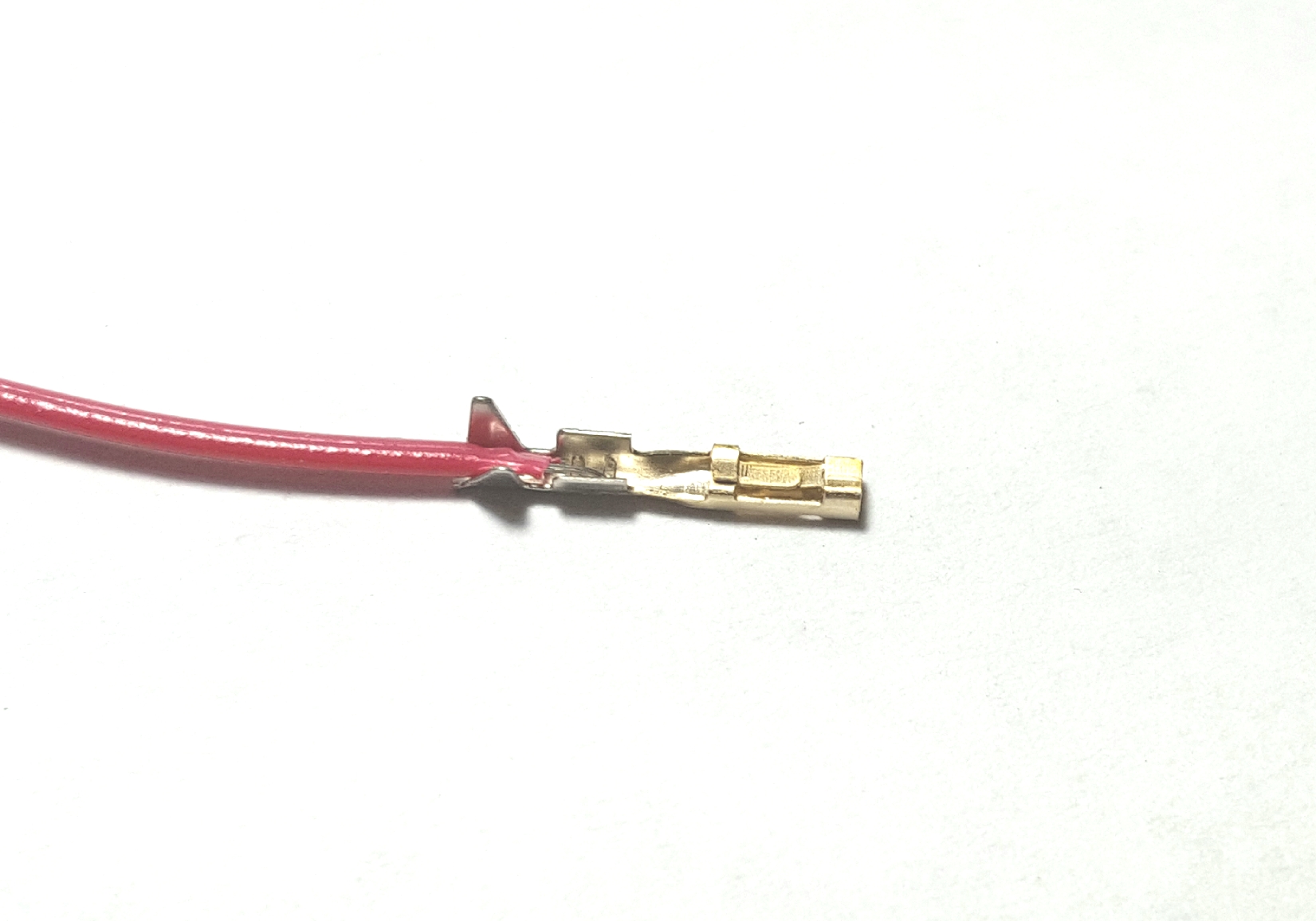
The above shows a good crimp.
Another way is to carefully fold portion of pin around stripped wire.
With needlenose pliers roll the back end of connector over the insulation
tightly. If it is not tight, it will not fit into the housing.
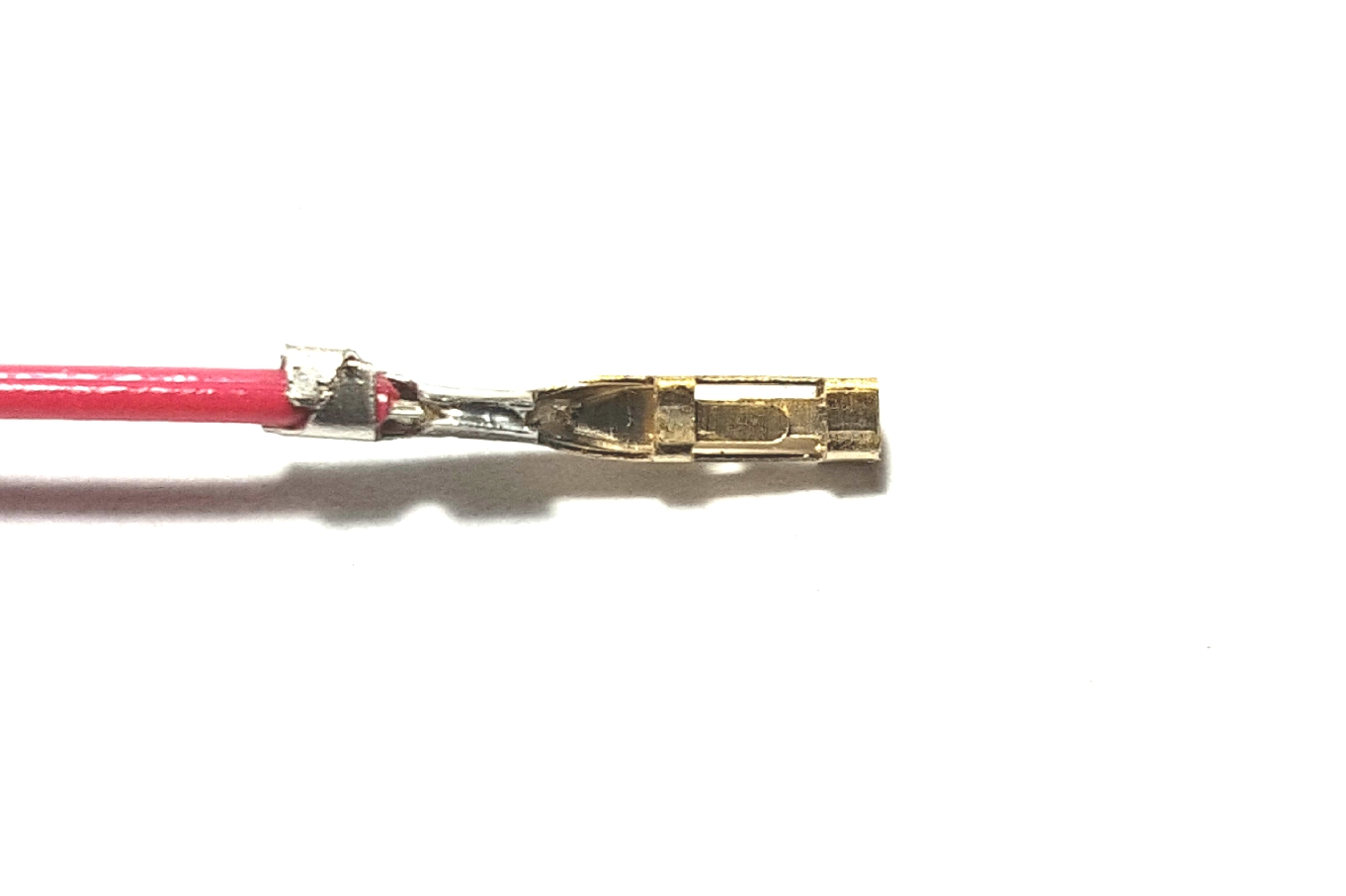
If you do not have a crimper you can very carefully solder wire to pin. Strip wire and
place in pin as shown above. Keep from overheating pin and wicking solder into
the contact portion and render it useless.
Using needlenose carefully roll the part of the pin around insulation. Be sure
to roll it tight otherwise it will not fit into the housing.
Push pinned wire into housing with solder side up and holes in housing up. They
should snap in with a click. If you tug on the wire, you should feel a little
play. It should feel loose. If you had to force the pin in and it is tight, you
have either too much solder or you didn't roll the pin in the needle nose pliers
to make it small enough to insert.
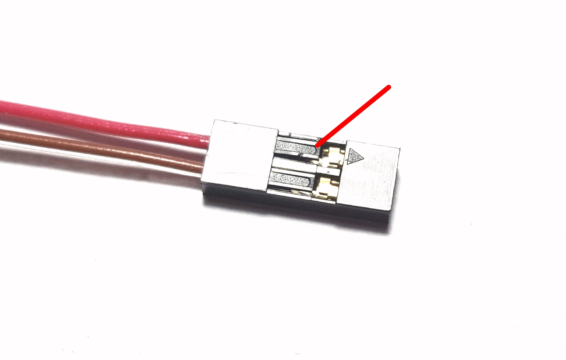
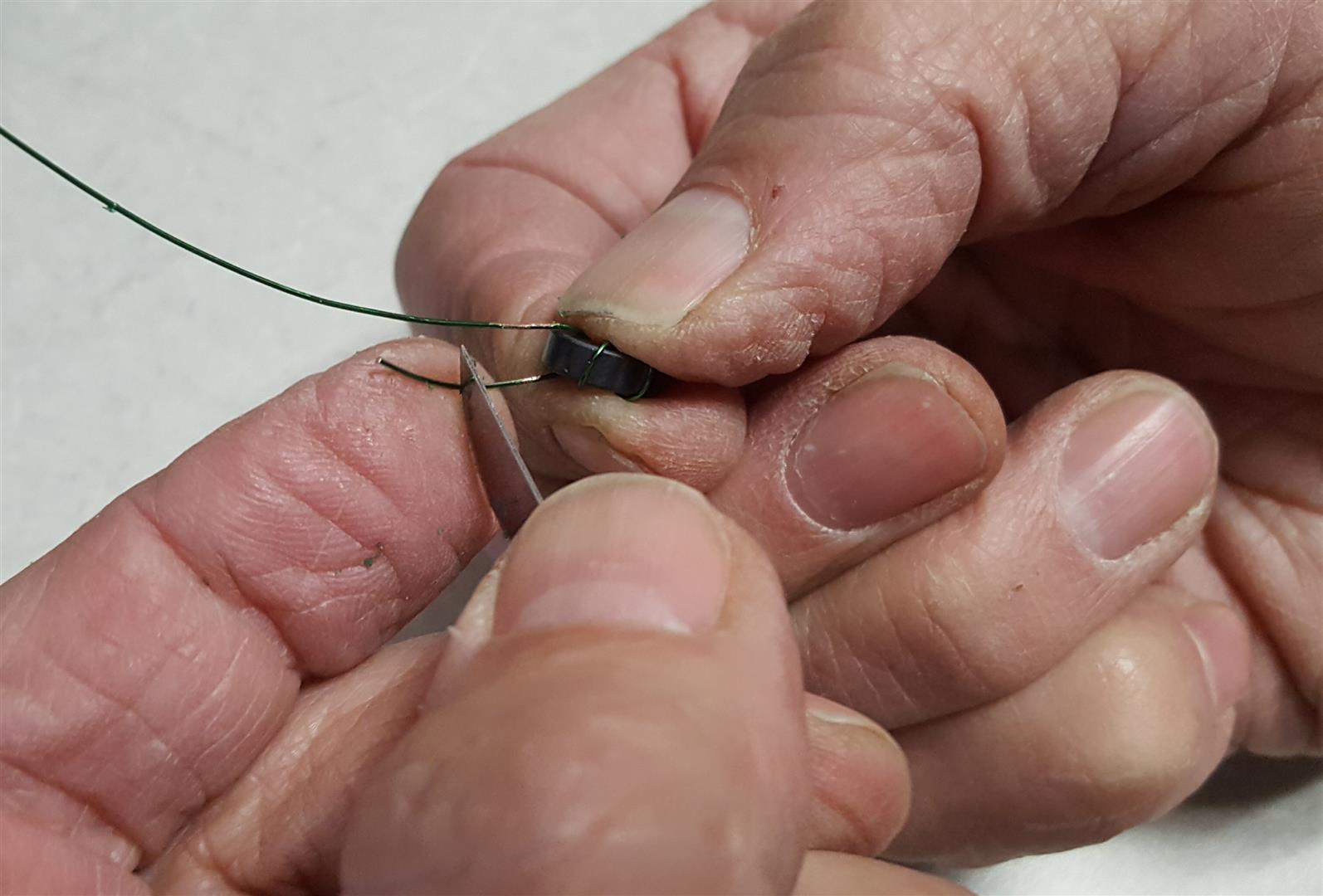
If you need to remove a wire you can insert a sharp blade shown with red pointer
to release the latch
on top of housing and pull wire out as shown in connector image above.
Using a knife or Xacto blade carefully scrape enamel insulation about a quarter
inch from the toroid body.
No need to scrape the whole length.
You can leave the wire leads long to ease inserting them into holes.
If you happen to mix the two Zeners up or can't read the values you can lash up a quick way to verify which one is the correct one. If you mix them up it may be a messy job swapping them because you could damage the board or destroy the fragile glass Zeners so make sure you test them if you cannot read them.
You could snap two 9 volt batteries together or use a variable power supply for the power source. The volt meter will show the Zener breakdown voltage.
Without the Zener in place the meter must display the voltage of the power source. Inserting the Zener will drop the displayed voltage to the Zener breakdown voltage. In the kit with two diodes you really only need to identify the 7.5 volt Zener
Remember, there are two Zeners in the ME+ kits, 7.5v and 33v, except for the ME20+ which has only one 7.5 volt Zener.
Updated March 27, 2023