Help! I can't tune in the right frequencies
(40 meter version)
Before finishing your kit you must decide what 35 to 40 khz span of
frequencies you want to work. Or, you might have completed the kit and can't find
the span of frequencies you desire.
We suggest you do not install the panel parts and board the enclosure.
Wire up all the
connections with the kit "spread eagled" on your test bench preferably
on a wood table or anti static mat. This will make it easier to turn the board
over, inspect your work, and do any troubleshooting or rework.
Leave C7 off until you have the transceiver fully functioning
on transmit and receive. Studying the right column on Page 13 you will see that
you should have a good carrier on transmit and receive somewhere around 7.230 with the
tuning pot at the highest tuning range, T2 and T3
peaked, and the R24 power adjust pot at just below the highest output power setting, around
1.70 watts. Do not exceed 2.0 watts! DO NOT proceed until you
fix the carrier frequency problem otherwise you'll be chasing after your desired
frequency span according to the table on page 13 of the manual.
If the frequency is too high, let's say 7330, check for improper
capacitor in the C3, 4, 5, 6, 8, 9 position, or it could be just an accumulation
of tolerances on those capacitors. It could also be the wrong number of turns on toroid
L1 and you may need to add a turn on L1 which means rewinding it. Or, simply
tack a spare capacitor like the 47, 68, or 82 pf cap in the bag of channeling
capacitors on the bottom of the board across L1 to get close to the magic 7.230
frequency. Before proceeding the transceiver
must be transmitting on around 7.230 in order for the desired frequency span
in the table to be correct with the channeling capacitors. Any substitution of
capacitors not contained in the kit must be C0G or NPO type so the CW tones
don't drift around with temperature changes.
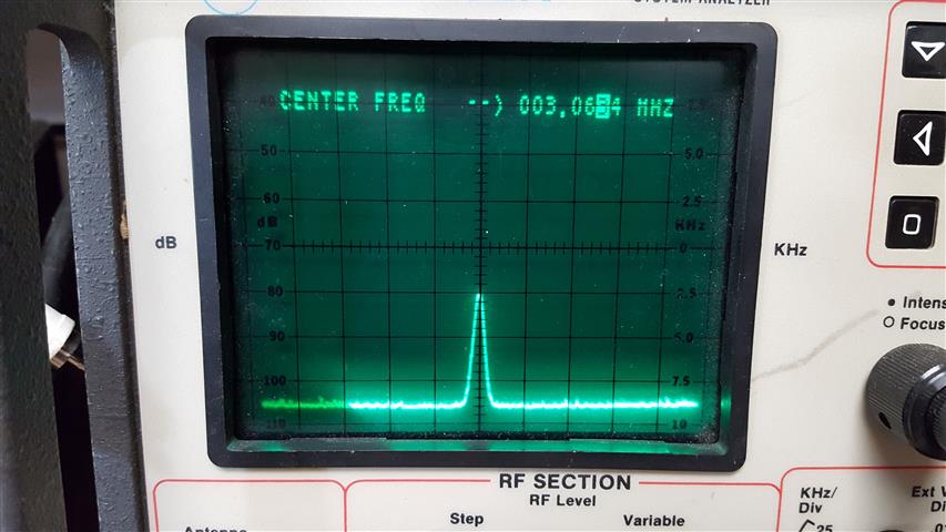
In the scan above, a 100 pf capacitor was installed in C7 and tuning knob was set in the
middle.
As you can see from the spectrum analyzer above, the VCO is sitting right on
3.065 which is exactly 4.000 mhz below desired frequency 7.065. Without C7 installed and tuning knob at highest setting there should be a carrier at around 3.230
khz (4 mHz below the desired 7.230 frequency).
From the above, you can troubleshoot the VCO (without transmitting
and overheating the output transistor) by tuning
your "big rig" to just below the 80 meter band to find your VCO frequency. A
small wire for an antenna from your "big rig" antenna input loosely placed near the
VCO which is around L1 toroid will help you hear the signal. This way you won't
have to be transmitting all the time when troubleshooting or selecting the C7
capacitor. With an antenna
connected to your kit you should tweak T1 for a maximum carrier from a received
signal. BE VERY CAREFUL TUNING THE TRANSFORMERS SO YOU DON'T PUSH TOO HARD AND
DESTROY THE TRANSFORMER!!!
With V1.1 and later versions of the circuitboard, there is a test point, TP1 which is the Local
Oscillator buffered output. This pin can be connected to the "big rig"
antenna input or eventually a digital frequency readout, of just a clip lead to
act as an antenna. TP1 is located just
above U1 pin 8.
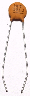
When selecting the C7 capacitor DO NOT solder it in place yet. Form the leads
on each C7 capacitor in a bowleg as shown below. This will make for a good
temporary contact and
keeps the capacitor from falling through board and possibly touching metal.
Place capacitor in C7 holes in circuitboard. It will make sufficient connections
to tune the local oscillator so you can select the correct value before
soldering.
Once you're satisfied you have the correct span of frequencies you can solder
C7 in place WITH POWER OFF. Peak T2 and T3 into a dummy load and adjust R24 for output power just
around 1.95 watts or so. An extra half watt or so won't give you a single db
more power and just consumes more power, increases heat on the output
transistor, and may cause instability. Try not to exceed 2.1 watts or you'll hear some RF getting
into other parts of the transceiver and you'll hear a raspy sidetone. Do not transmit without a load
connected. You will damage the output transistor.
|
Make sure your power supply is at least 12.6 volts.
Anything lower can cause reduced output power and unstable CW carrier
or garbled receive. |
Some of you might want to put a switch in to change C7 to select different
areas of the 40 meter band to operate. This can be easily done since one end of C7 is
ground. You may have to play with the C7 values since you are adding stray capacitance
to the VCO tank circuit and the published frequencies on Page 13 will be
slightly off. You can fine tune your desired span using junk box capacitors as
long as they are temperature stable NPO or C0G types. Otherwise slight
temperature changes will cause your desired frequency to drift.
If you want to replace the tuning pot with a 10 turn pot, you may want to
also replace C8 with a higher value to span about 100khz. But do not expand any
further due to instability. The C7 values will need to be juggled around to set
your desired range too. See
this page for hints.